Main technical parameter
Application

| Main technical parameter | |||||
| ALJ12A3-series | |||||
| Model | DC 3-wire type NPN type | NC | ALJ12A3-02-Z/AX | ALJ12A3-04-Z/AX | |
| NO | ALJ12A3-02-Z/BX | ALJ12A3-04-Z/BX | |||
| NO/NC | ALJ12A3-02-Z/CX | ALJ12A3-04-Z/CX | |||
| DC 3-wire type PNP type | NC | ALJ12A3-02-Z/AY | ALJ12A3-04-Z/AY | ||
| NO | ALJ12A3-02-Z/BY | ALJ12A3-04-Z/BY | |||
| NO/NC | ALJ12A3-02-Z/CY | ALJ12A3-04-Z/CY | |||
| DC 2-wire type | NC | ALJ12A3-02-Z/DX | ALJ12A3-04-Z/DX | ||
| NO | ALJ12A3-02-Z/EX | ALJ12A3-04-Z/EX | |||
| AC 2-wire type | NC | ALJ12A3-02-J/DZ | ALJ12A3-04-J/DZ | ||
| NO | ALJ12A3-02-J/EZ | ALJ12A3-04-J/EZ | |||
| Installation | Embedded | Non-embedded | |||
| Sensing distance | 2mm | 4mm | |||
| Setting distance | 0~1.4mm | 0~2.8mm | |||
| Hysteresis | Max.10% of sensing distance | ||||
| Standard sensing target | 12×12×1mm(Iron) | ||||
| Power supply(Operating voltage) | 6~36VDC/90~250VAC | ||||
| Leakage current | Max.10mA | ||||
| Response frequency(※1) | DC 1500Hz/AC 20Hz | ||||
| Residual voltage | DC 3-wire type Max.1.0V/DC 2-wire type Max.3.5V/AC 2-wire type Max.10V | ||||
| Affection by temp. | Max.±10% for sensing distance at ambient temperature 20℃ | ||||
| Control output | Max.200mA | ||||
| Insulation resistance | Min.50MΩ(at 500VDC) | ||||
| Dielectric strength | 1500VAC 50/60Hz 1minute | ||||
| Vibration | 1mm amplitude at frequency of 10 to 55Hz(for 1 min.)in each of X,Y,Z directions for 2 hours | ||||
| Shock | 500m/s2(approx.50G)X,Y,Z directions for 3 times | ||||
| Indicator | Operation indicator(red LED) | ||||
| Ambient temperature | -25~+70℃( No icing) | ||||
| Storage temperature | -30~+80℃(No icing) | ||||
| Ambient humidity | 35~95%RH(No condensation) | ||||
| Protection | IP67 | ||||
Features
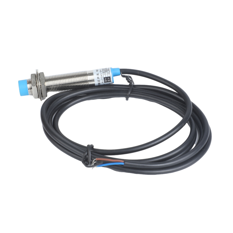
Looking for a high-performing and reliable device that conforms to industry regulations and standards? Look no further than our advanced proximity sensors! Our sensors are equipped with a range of features that enable them to deliver optimal performance and unparalleled reliability, making them ideal for a wide variety of operations. This includes fast response, high repetition accuracy, excellent anti-interference performance, compact design, and vibration resistance. Our proximity sensors are also effortless to install and calibrate, reducing downtime and increasing productivity. Plus, they have an extensive service life, ensuring minimal maintenance costs over time. Users will also find red LED indicators that make it easy to identify the operating status, further improving efficiency and reducing downtime. These sensors are highly versatile and can be used instead of micro switches or limit switches, making them an excellent investment for individuals looking for an affordable, high-quality switch solution. Trust us to deliver a product that exceeds expectations and provides optimal results.Control Output Diagram
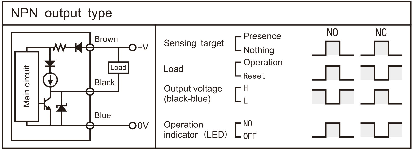
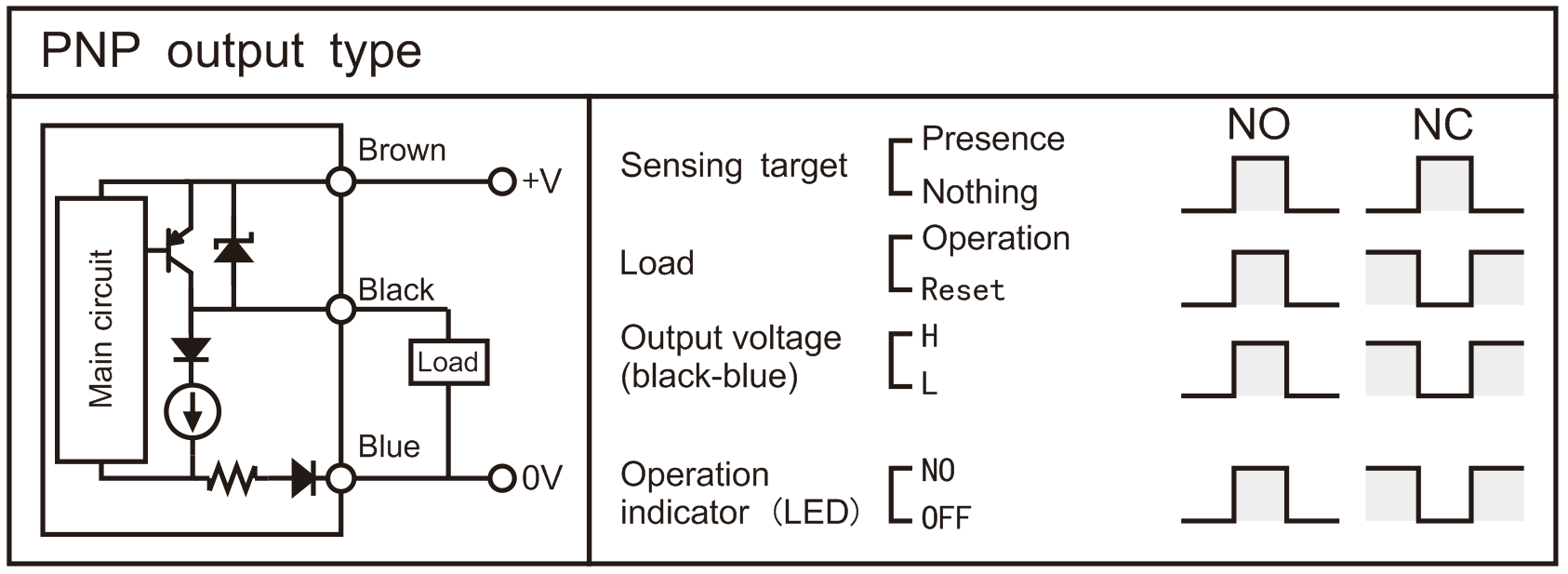
| DC 3-wire type |
| DC 2-wire type |
| AC 2-wire type |


Proper Usage
| "Sn" in the table is the detection distance | ||
| Type Item | Inductive proximity switch | Capacitive proximity switch |
| A | ≥5Sn | ≥10Sn |
| B | ≥4Sn | ≥10Sn |
| C | ≥2Sn | ≥3Sn |
| D | ≥3Sn | ≥3Sn |
| ΦE | ≥4d1 | ≥6Sn+d1 |
1. Mutual interference
More than two proximity switches are shown in the figure below. When they are installed face to face or in parallel, the frequency interference is easy to cause misoperation. Pay attention to the distance between products when installing them (there are notes in the figure below).
- Influence of surrounding metal
If there is metal around the proximity switch, it will lead to poor reset and other misoperation. In order to prevent misoperation caused by the surrounding metal, attention should be paid to the distance between the product and the metal during installation (there are notes in the figure below).
Connections
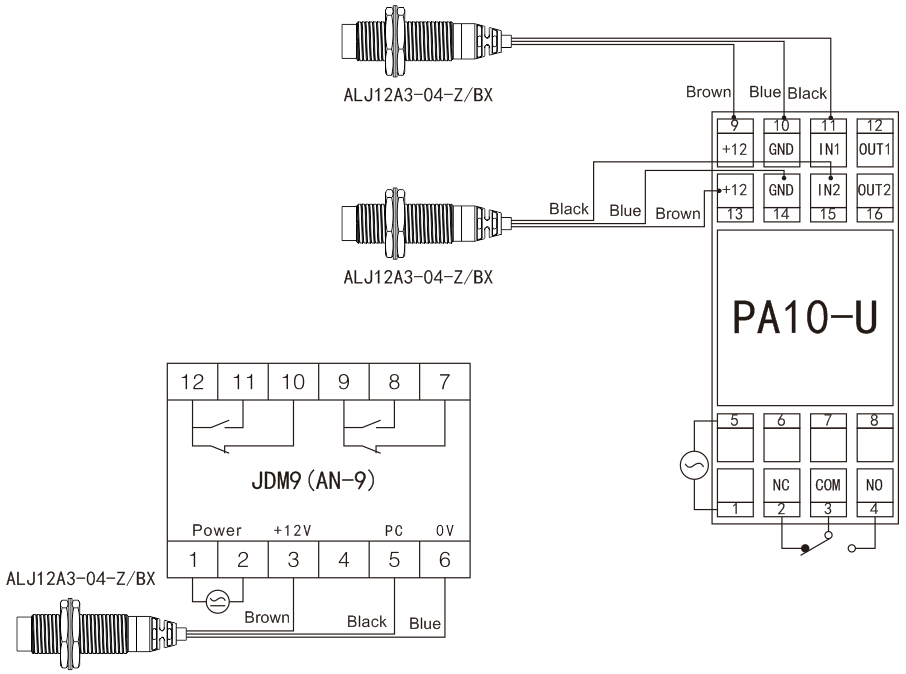
| DC 3-wire type |
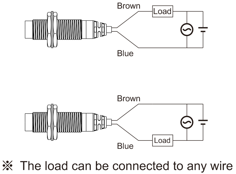
| AC and DC 2-wire type |
