Main technical parameter
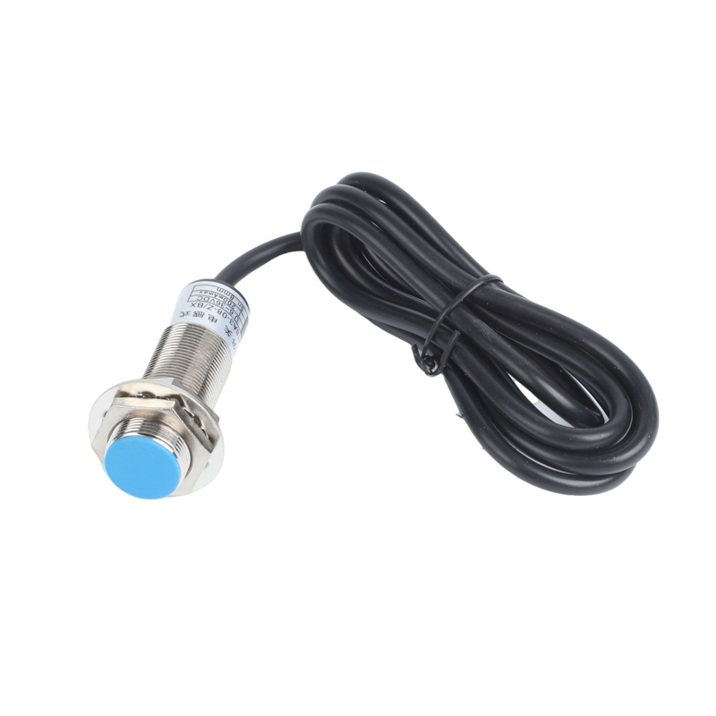
(1) Company code (2) Proximity switch LJ-inductive type CJ-capacitive type (3) Diameter 8: 8mm 12: 12mm 18: 18mm 30: 30mm (4) Structure A: Cylindrical (5) Shell material 3: metal (6) Detection distance 1:1mm 2:2mm 3:3mm 4:4mm 5:5mm 8:8mm 10:10mm (7) Working voltage Z: DC6~36V J: AC90~250V (5) Output type A: Three-wire NC B: Three-wire NO C: Four-wire NO/NC D: Two-wire NC E: Two-wire NO (8) Output current X: NPN (200mA) Y: PNP (200mA) Z: 300~400mAApplication

Model Number Structure
Features
| ●Conform to GB/T14048.10 and many other national or industry standards. |
| ●Provided with many features of small size, fast response, high repetition accuracy, wide voltage range, good anti-interference performance, no mechanical wear, no spark, no noise, vibration resistance, convenient installation and calibration, long service life and so on. |
| ●Red LED status indicators for easy identification of operating status. |
| ●Widely used instead of micro switch or limit switch. |
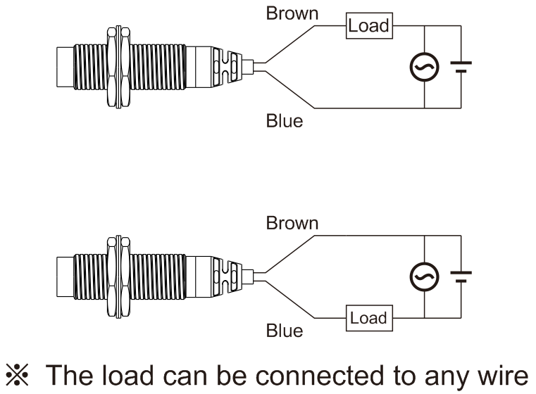
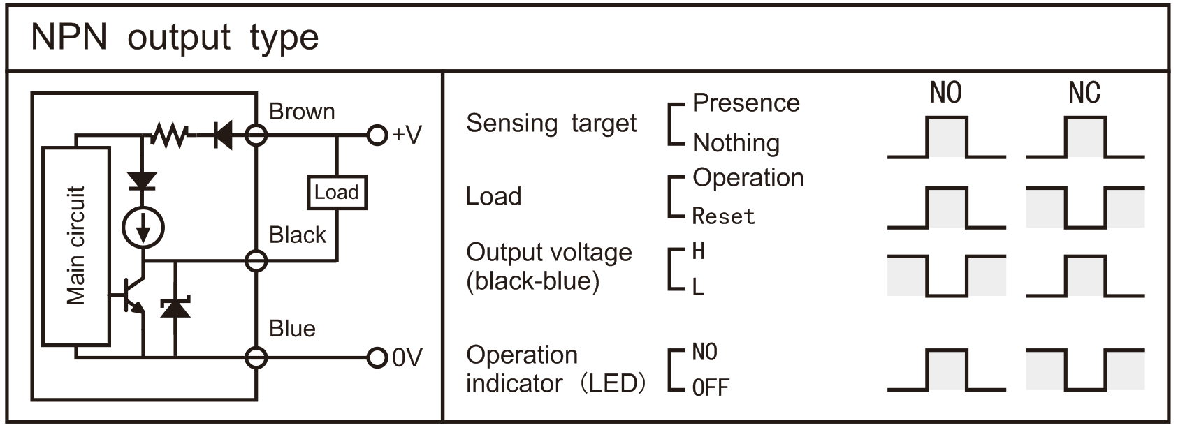
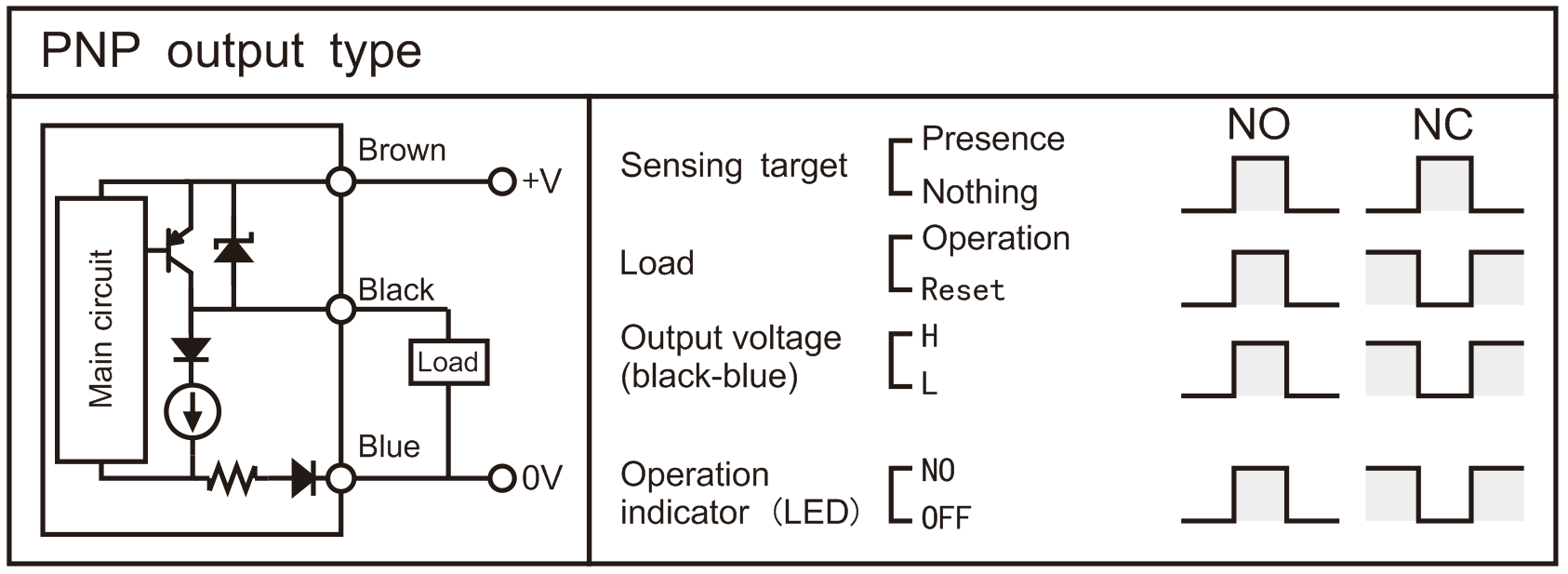
Control Output Diagram
| DC 3-wire type |
| DC 2-wire type |
| AC 2-wire type |


Proper Usage
| "Sn" in the table is the detection distance | ||
| Type Item | Inductive proximity switch | Capacitive proximity switch |
| A | ≥5Sn | ≥10Sn |
| B | ≥4Sn | ≥10Sn |
| C | ≥2Sn | ≥3Sn |
| D | ≥3Sn | ≥3Sn |
| ΦE | ≥4d1 | ≥6Sn+d1 |
1. Mutual interference
More than two proximity switches are shown in the figure below. When they are installed face to face or in parallel, the frequency interference is easy to cause misoperation. Pay attention to the distance between products when installing them (there are notes in the figure below).
- Influence of surrounding metal
If there is metal around the proximity switch, it will lead to poor reset and other misoperation. In order to prevent misoperation caused by the surrounding metal, attention should be paid to the distance between the product and the metal during installation (there are notes in the figure below).
| ALJ18A3- series | |||||
| Model | DC 3-wire type NPN type | NC | ALJ18A3-05-Z/AX | ALJ18A3-08-Z/AX | |
|
|
| NO | ALJ18A3-05-Z/BX | ALJ18A3-08-Z/BX | |
|
|
| NO/NC | ALJ18A3-05-Z/CX | ALJ18A3-08-Z/CX | |
|
| DC 3-wire type PNP type | NC | ALJ18A3-05-Z/AY | ALJ18A3-08-Z/AY | |
|
|
| NO | ALJ18A3-05-Z/BY | ALJ18A3-08-Z/BY | |
|
|
| NO/NC | ALJ18A3-05-Z/CY | ALJ18A3-08-Z/CY | |
|
| DC 2-wire type | NC | ALJ18A3-05-Z/DX | ALJ18A3-08-Z/DX | |
|
|
| NO | ALJ18A3-05-Z/EX | ALJ18A3-08-Z/EX | |
|
| AC 2-wire type | NC | ALJ18A3-05-J/DZ | ALJ18A3-08-J/DZ | |
|
|
| NO | ALJ18A3-05-J/EZ | ALJ18A3-08-J/EZ | |
| Installation | Embedded | Non-embedded | |||
| Sensing distance | 5mm | 8mm | |||
| Setting distance | 0~3.5mm | 0~5.6mm | |||
| Hysteresis | Max.10% of sensing distance | ||||
| Standard sensing target | 18×18×1mm(Iron) | ||||
| Power supply(Operating voltage) | 6~36VDC/90~250VAC | ||||
| Leakage current | Max.10mA | ||||
| Response frequency(※1) | DC 1500Hz/AC 20Hz | ||||
| Residual voltage | DC 3-wire type Max.1.0V/DC 2-wire type Max.3.5V/AC 2-wire type Max.10V | ||||
| Affection by temp. | Max.±10% for sensing distance at ambient temperature 20℃ | ||||
| Control output | Max.200mA | ||||
| Insulation resistance | Min.50MΩ(at 500VDC megger) | ||||
| Dielectric strength | 1500VAC 50/60Hz 1minute | ||||
| Vibration | 1mm amplitude at frequency of 10 to 55Hz(for 1 min.)in each of X,Y,Z directions for 2 hours | ||||
| Shock | 500m/s2(approx.50G)X,Y,Z directions for 3 times | ||||
| Indicator | Operation indicator(red LED) | ||||
| Ambient temperature | -25~+70℃( No icing) | ||||
| Storage temperature | -30~+80℃(No icing) | ||||
| Ambient humidity | 35~95%RH(No condensation) | ||||
| Protection | IP67 | ||||
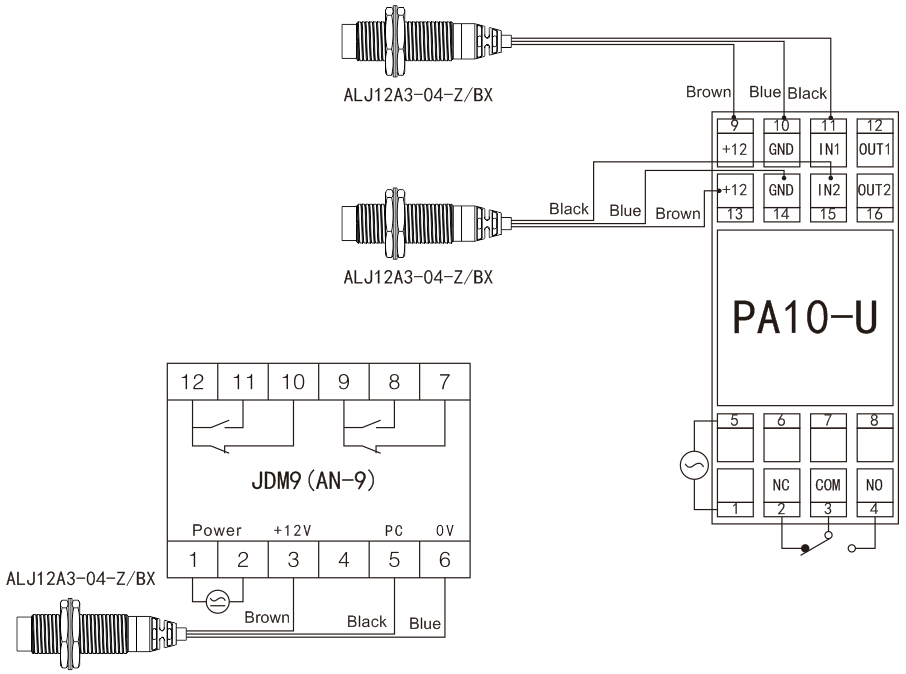
Connections
| DC 3-wire type |
| AC and DC 2-wire type |
