Main technical parameter
| Delay range code | 1 | 2 | 3 | 4 | 5 | 6 | 7 | 8 | 9 |
| Nominal delay range | 0.1s~1s | 1s~10s | 3s~30s | 6s~60s | 12s~120s | 18s~180s | 30s~300s | 60s~600s | 90s~900s |
| Note: The special delay specification order shall be agreed between the user and the manufacturer. | |||||||||
Application

| Working power | AC380V、220V、110V、36V、24V 50Hz;DC24V; |
| Mode | Power on delay/Poweron cycle delay |
| Repeat error | ≤3% |
| Number of contacts | a groups of changeover |
| Delay range | S:0.01s~99.99s M:1s~99m59s H:1m~99h59m |
| Contact capacity | Ue/Ie:AC-15 AC220V/1A;DC-13 DC220V/0.15A;Ith:3A |
| Mechanical life | 1×10⁶ time |
| Electrical life | 1×10⁵ time |
| Installation | Device type |
Model Number Structure
Features
| ● Standard outline dimensions (96 × 86mm), convenient opening. |
| ● Conform to many national or industry standards such as GB/T14048.5 withvhigh quality and high performance. |
| ● Adopt integrated circuits as the main components with a wide delay range. |
| ●Provided with many advantages such as long life, small size, light weight and so on. Widely used in various automatic control systems that require high precision and high reliability. |
Wiring diagram

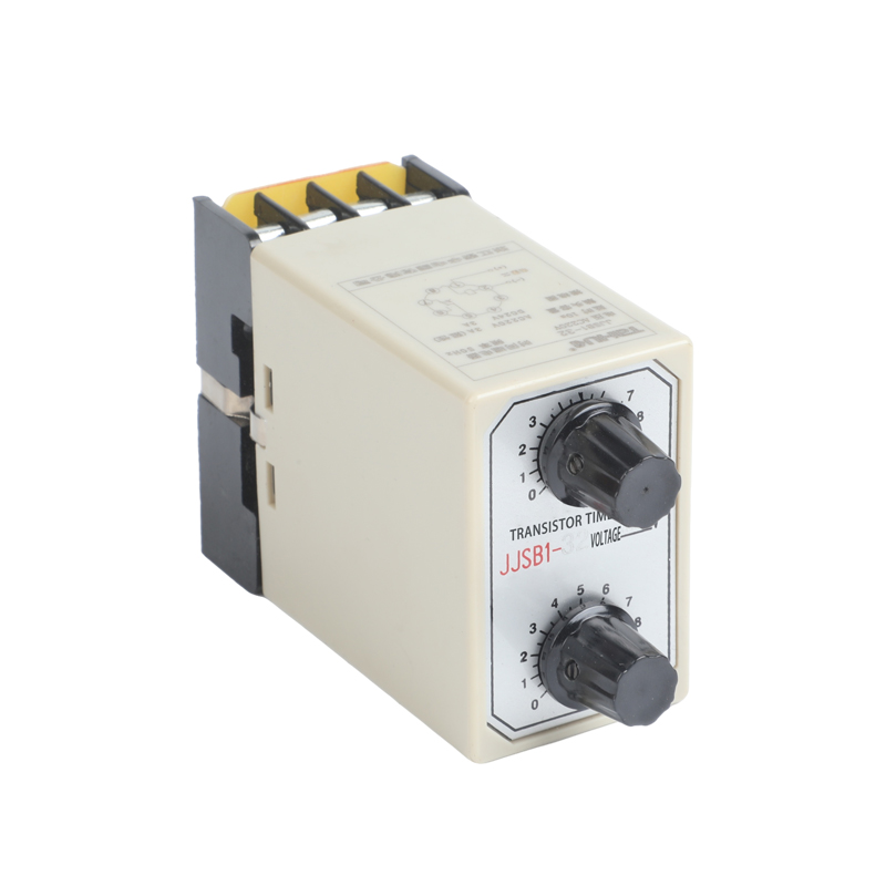
Outline and installation dimensions
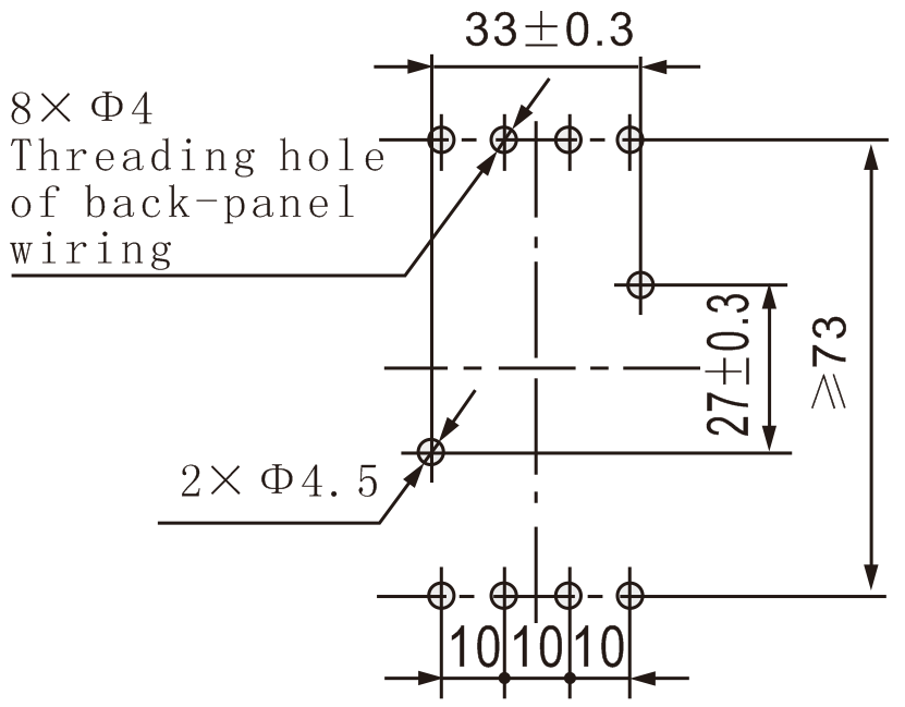
Installation dimensions diagram

Power-on delay type 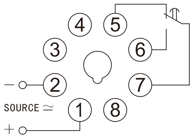 | Power-on delay external type 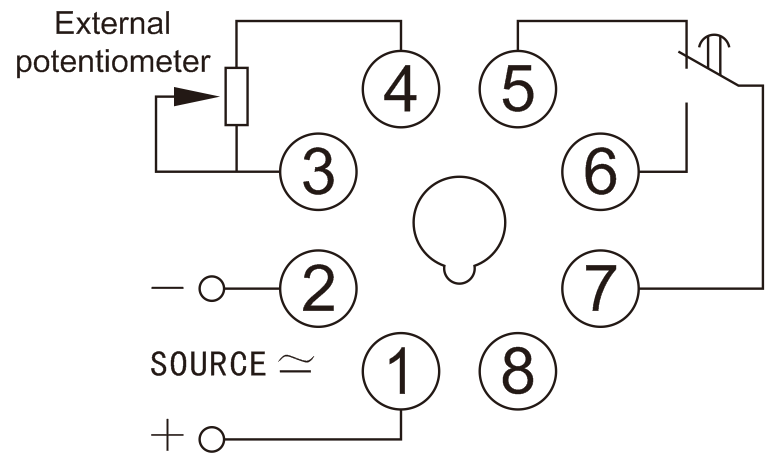 |
Cycle delay type 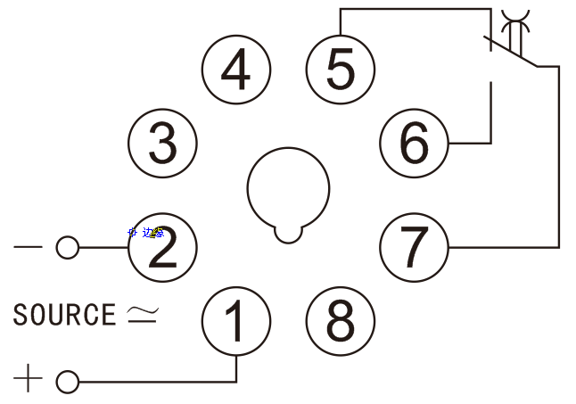 |
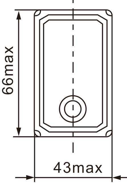
Power-on delay external type
(1) Transistor (2) Time relay (3) Design serial number (4) Derived code 1: AC power-on delay 2: DC power-on delay 3: AC cycle delay 4: DC cycle delay (5) Delay range Code See the Table (6) Installation method None: Socket type Y: External delayOutline dimensions diagram
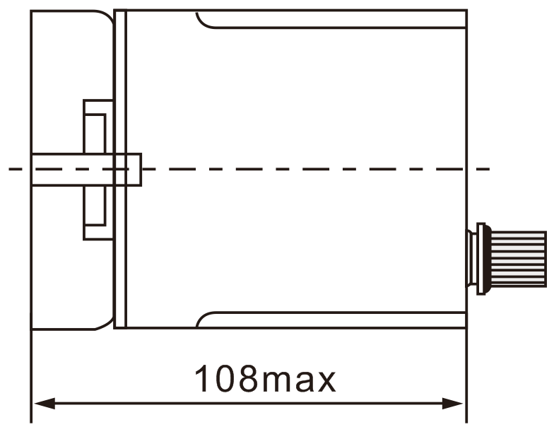
Power-on delay type
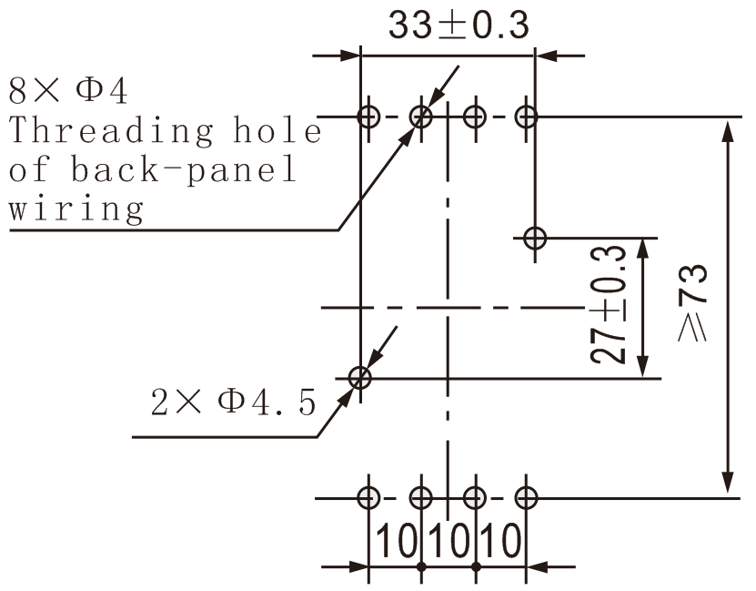
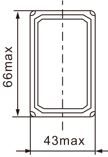
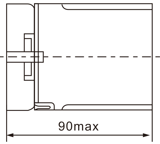
Installation dimensions diagram
Outline dimensions diagram
